Creating an IEC-268 Baffle
In 2023, I created this IEC-268 baffle to improve the accuracy and consistence of my acoustic measurements at work.
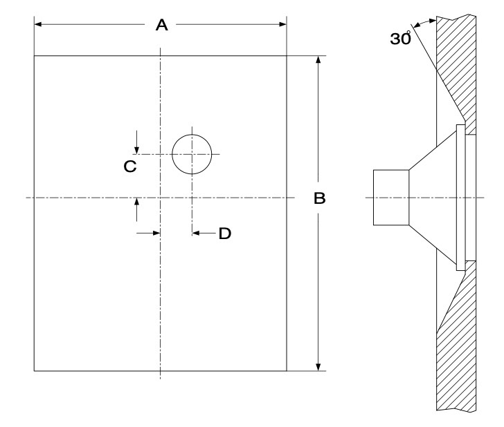
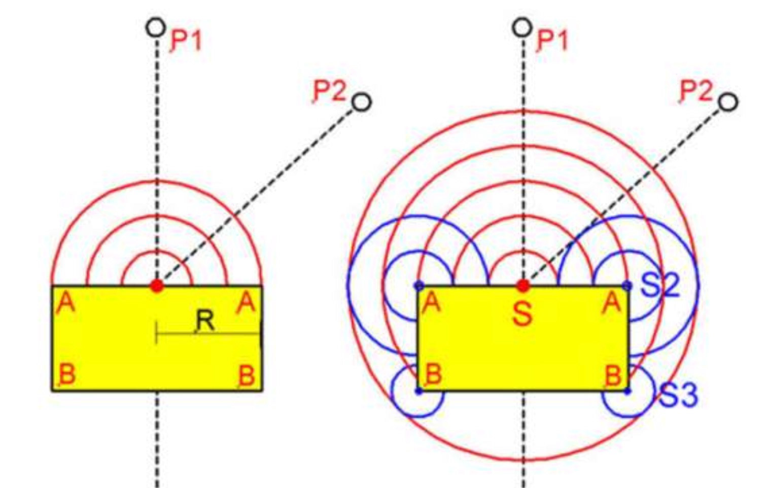
When acoustic waves travels in air and meet a sharp edge, edge diffraction occurs. Diffracted waves will travel with direct waves from the speaker and skew the loudspeaker measurement. As we can see in the following image, as the direct wave from the source travel across the speaker enclosure and hit the corners, secondary sources are formed and start to radiate sound as well. If not controlled, edge diffraction will inevitably impact the accuracy of my measurements.
Standardization in testing is essential for making repeatable tests, not only here at our lab, but also across different labs in other parts of the world. The IEC 268-5 baffle standard is well established and used by many labs around the world. Having a baffle of the same size will make it easier to compare my results with results from other labs. Creating a testing procedure based on mounting the speaker under test inside the baffle will also improve the repeatability of my tests.
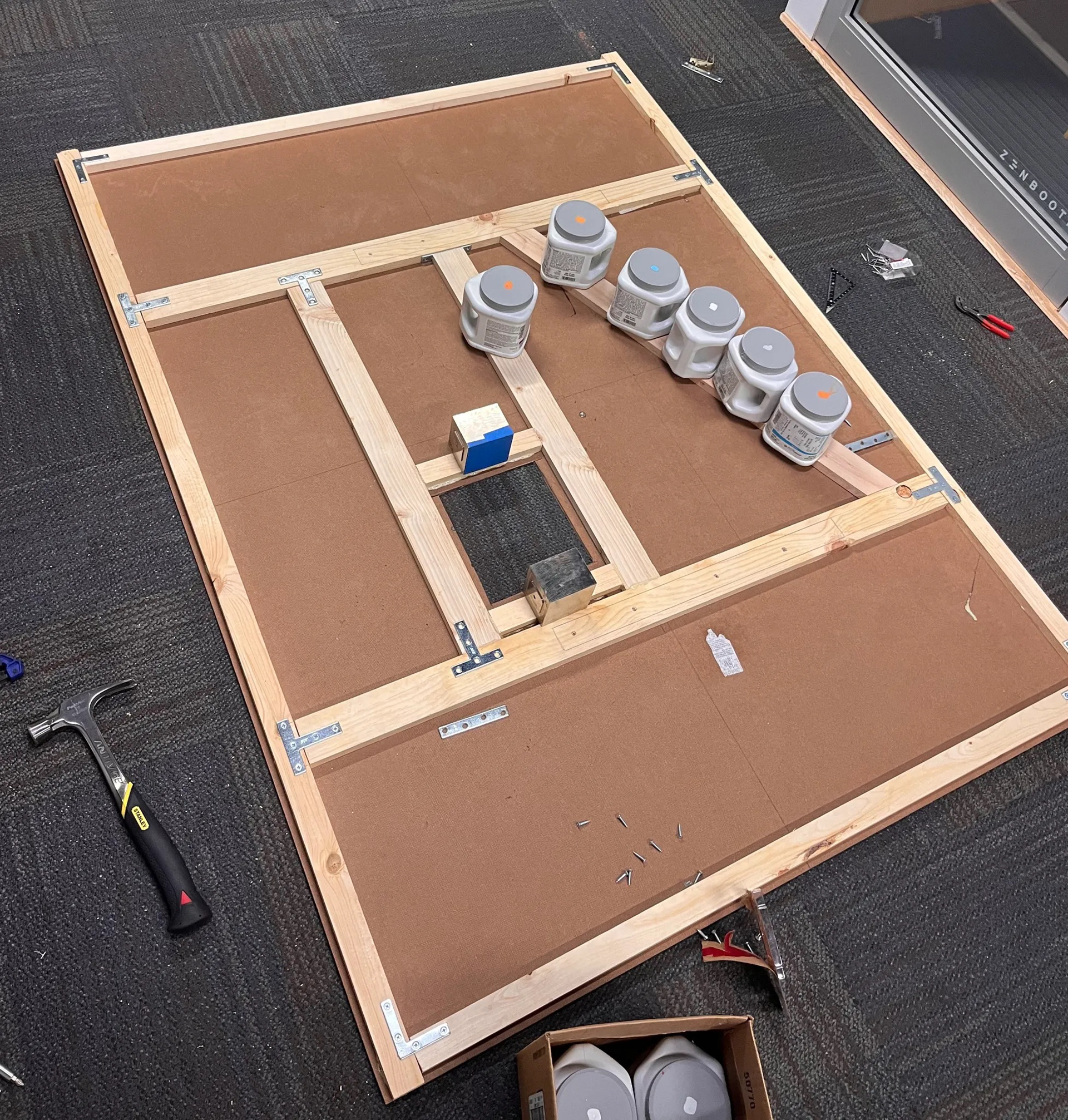
It’s time to start building the baffle. We’re using 1/4-inch hardboard for the baffle due to its flat, hard, and smooth surface, which is ideal for sound reflection. Additionally, we opt for smaller wood boards to be attached to the back, acting as a frame to provide much-needed stiffness to the baffle. Furthermore, I mounted the entire baffle on a large TV stand with wheels, allowing me to easily move it around the office.
For speaker mounting, I made a rectangular cutout on the baffle using a Dremel tool and installed some hold-down clamps around it. This allows me to mount various loudspeakers and loudspeaker enclosures to the baffle with 3D printed mounts. A fast 3D printer capable of producing these types of inserts in just a few hours, greatly improves my efficiency and turnaround time in testing speakers. Custom 3D printed mounts also ensure maximum flatness and precision on the front side of the baffle.
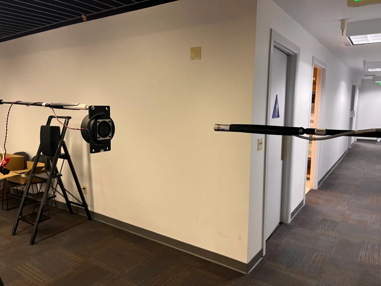
After construction, it’s time to mount some speakers for testing. To compare speaker measurement results with and without the baffle, we chose a 1-inch speaker enclosure.We measure this speaker enclosure in the near field, in free field, and on the IEC baffle and compare the results.
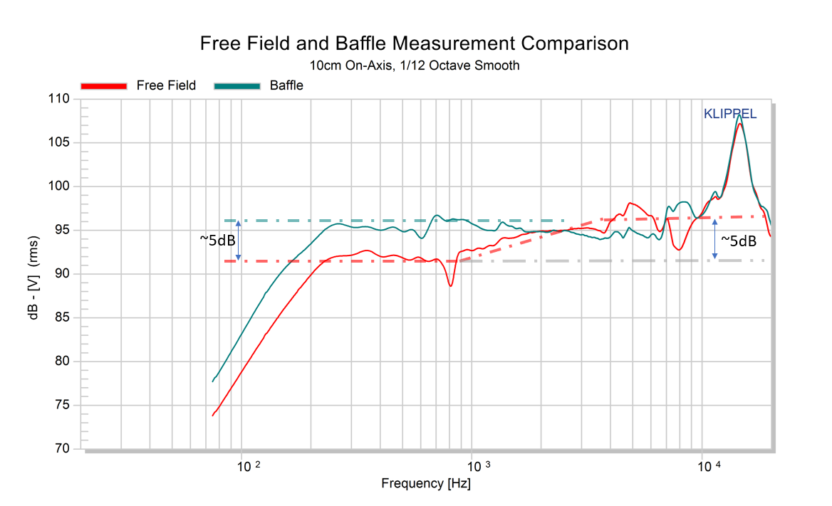
We can see that the shape of the free field result (red curve) generally follows the “baffle step” curve shape — meaning that baffle step is indeed an issue in this type of measurement. The sharp dip at 800Hz is from the resonance of the measurement setup. If we look at where the amplitude starts to drop, we see it is around 3kHz. By measuring the distance from the center of the loudspeaker to the edge of the small circular baffle, we can get a quick estimation of when the baffle step should occur. The distance is 3.5cm, corresponding to a diffracted time delay of 0.102ms. From this, we can calculate that max constructive interference between the direct and diffracted sound will happen at 1s/(0.102 ms*2) = 4.9kHz. This seems to align closely with the peak we see at around 5kHz in the free field measurement. Destructive interference will happen when the time delay corresponds to 1/4 period or less, which corresponds to a frequency (at 1/4 period) of 1 s/(0.102ms*4) = 2.5kHz. Below this frequency we see destructive interference between he direct and diffracted sound, and thus the “step” is formed. In my measurement, the magnitude of the “step” is around 5dB, slightly less than the theoretical 6dB. This is likely caused by reflections in the room also picked up by the measurement mic.
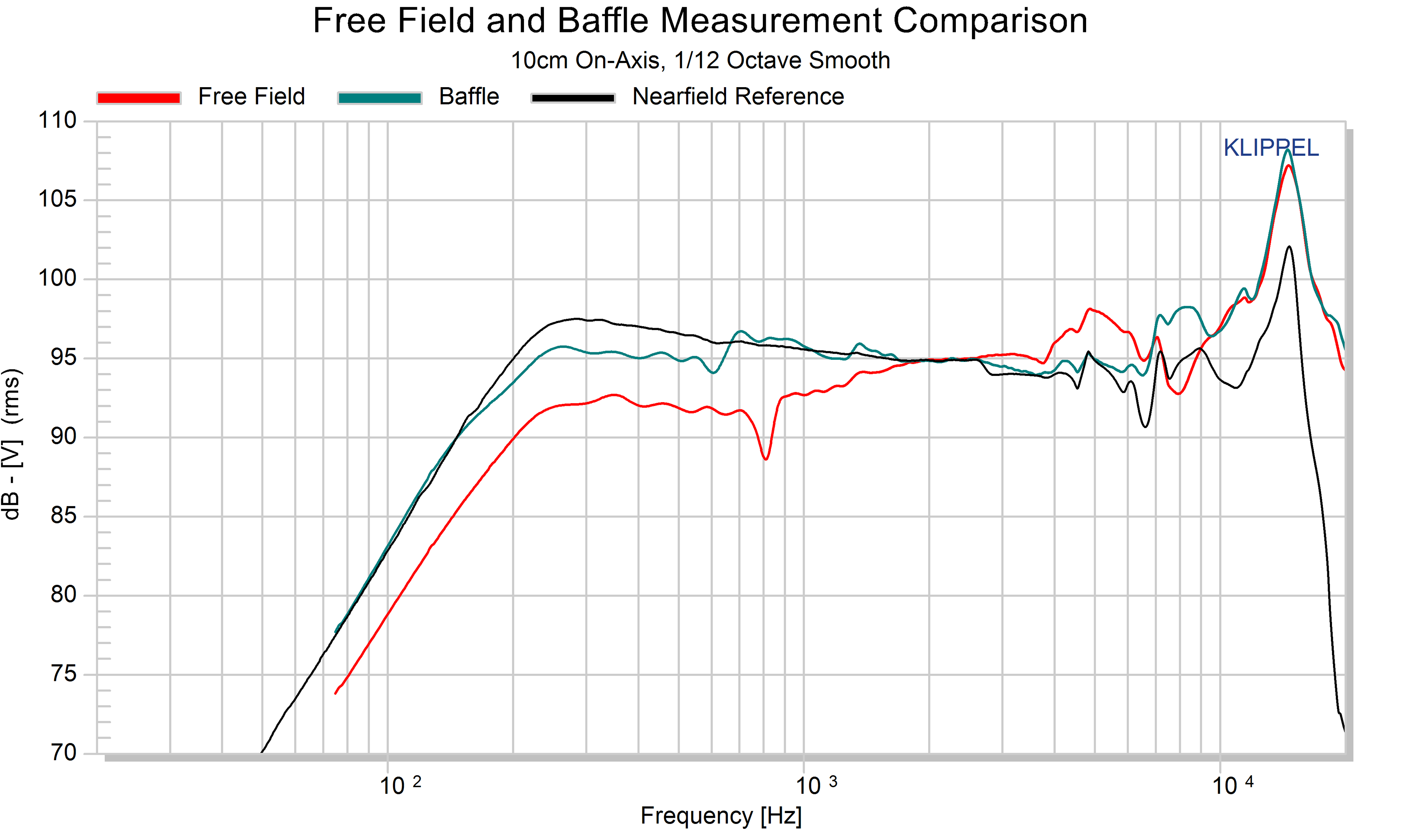
We also compare the baffle measurement to a nearfield measurement, which does not suffer from room reflections or baffle effects. The nearfield measurement technique is not full range, and its upper frequency limit is determined by the effective cone diameter D: Fmax = 10950/D where D is in centimeters. For this speaker, we determined that Fmax = 3.1kHz. As we can see, the baffle measurement follows the nearfield measurement very closely below 3.1kHz while providing more accurate information at higher frequencies above 3.1kHz. The IEC baffle is making my measurements more accurate and repeatable. Noted acoustic engineers and loudspeaker designers Philip Newell and Keith Holland said in their book, “Measurement has driven analysis, and analysis has driven design.” I will continue to sharpen my acoustic measurement skills and discover more intricacies of the acoustic world.